How to Choose a Valve Positioner
Choosing a Valve Positioner is not just a matter of matching a model number to an actuator. The right device helps a control valve respond accurately to changing signals, maintain stable operation, and support the needs of the process. A poor match can cause sluggish movement, hunting, excess air use, or difficult commissioning. Small details matter.
Start with the valve and actuator in front of you. Check actuator type, required travel, available air supply, input signal, and mounting arrangement. Then consider operating temperature, vibration, moisture, and any hazardous-area requirements relevant to the installation. Digital positioners may offer diagnostics and easier configuration, while simpler pneumatic models can suit less complex duties. Neither is automatically better. The process conditions decide.
This guide examines practical selection factors, including sizing, feedback, communication protocols, fail-safe behavior, and maintenance needs. It also explains why compatibility with the control system and clear setup instructions matter after installation. A neat specification sheet can still hide a poor fit for real operating conditions, so confirm assumptions with equipment documentation and qualified technical support. Test it. A careful choice can improve control performance, but no positioner can compensate for an incorrectly sized valve or actuator. The goal is a dependable match that can be configured, verified, and maintained throughout the valve’s service life.
Identify the Valve and Control Requirements
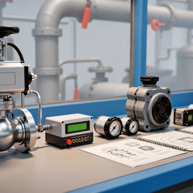
Before choosing a positioner, identify the valve’s motion and actuator. A linear globe valve needs a different setup from a quarter-turn ball or butterfly valve. Check the nameplate, stem travel, actuator spring range, and available air supply. Then confirm the control signal, required travel time, and fail position. On site, measure actual stroke; drawings can be out of date. Small mismatch, big trouble.
Define what the loop must control: pressure, flow, temperature, or level. Note normal and peak operating conditions, expected throttling range, and whether the valve must handle frequent reversals. The U.S. Energy Information Administration’s Monthly Energy Review attributes about 35% of U.S. primary energy use to the industrial sector in 2023. That figure is not a valve-performance measure, but it shows why stable process control matters. For a positioner, specify the input signal, feedback method, response needs, hazardous-area classification, and ambient conditions. Check air quality and supply pressure at the instrument, not only at the compressor. A clean datasheet helps, yet it may not capture sticky packing or vibration. Verify those conditions during a site walkdown; I would not assume the installed valve behaves like a new one.
How to Choose a Valve Positioner: Identify the Valve and Control Requirements
Confirm the valve and actuator type, required travel and action, available air supply, and control signal before selecting a positioner. This chart shows an ideal linear mapping for a common 4–20 mA command: 4 mA corresponds to 0% travel, and 20 mA to 100%. Actual positioner setup may use a different characterization. A common pneumatic command range is 3–15 psi.
Match the Positioner Type to the Actuator and Valve
How to Choose a Valve Positioner
Match the positioner to both the actuator and the valve, not just the control signal. A linear globe valve needs a positioner suited to straight stem travel. A rotary ball or butterfly valve needs one that follows angular movement. Check the actuator’s stroke or rotation range, mounting pattern, and linkage. A loose bracket can cause sluggish response or position errors. Small details matter.
Then consider the actuator’s operating style. A spring-return actuator usually needs a positioner configured for its single-acting air circuit. A double-acting actuator requires suitable outputs for air to both sides. Also verify the input signal, available air supply, and required feedback. Pneumatic and electropneumatic models suit different control systems; digital models can add diagnostics, but only when those features are useful and supported. I have seen selection sheets overlook travel range. That is easy to regret during commissioning.
Tips: Before ordering, compare the valve data, actuator manual, and positioner specifications. Confirm travel direction and linkage alignment on the assembled unit. If the actuator or valve has been modified, recheck the fit instead of relying on an old drawing. Test movement through the full stroke, slowly. Small mismatches show up early.
Check Signal, Power, and Communication Compatibility
Before selecting a valve positioner, match its input signal to the control system. A common loop uses 4–20 mA, but confirm whether the controller sends an analog signal alone or uses HART communication. NAMUR NE 43 identifies signal levels below 3.6 mA and above 21 mA as fault indications; check that the positioner interprets these levels as intended. Small differences matter. A mismatch can make a fault look like a valid command.
Power and wiring deserve equal attention. Read the positioner’s voltage range, then calculate what remains after cable losses, barriers, and other loop loads. For HART, verify that loop resistance supports communication; around 250 ohms is commonly used, but the device documentation takes precedence. FieldComm Group reports more than 40 million HART-enabled devices installed worldwide, yet that reach does not make every HART device compatible with every control system. Confirm the protocol version, available configuration tools, and whether digital communication can coexist with the analog signal. A neat drawing may still hide a grounding or resistance problem. Check the loop at the terminals, not only on paper.
How to Choose a Valve Positioner - Check Signal, Power, and Communication Compatibility | Positioner Type | Typical Control Signal | Power or Air Supply | Communication Compatibility | Key Checks Before Selection |
| Analog electro-pneumatic | Commonly 4–20 mA DC; verify whether the input is configured for the required range and whether the device is loop-powered. | Instrument air is required for actuator operation. Many designs use the input loop for electronics; some require a separate power supply. | Usually no digital communication. Confirm whether a communication option is needed for setup or diagnostics. | Match the input signal, electrical load, air quality and pressure range, actuator action, and required travel direction. |
| Digital positioner with HART | Typically 4–20 mA DC with a superimposed HART digital signal. | Usually requires instrument air. Electronics may be loop-powered or may require separate power, depending on the device. | Requires HART-compatible configuration equipment and a loop that allows the communication signal to pass. Check for barriers or isolators that may affect communication. | Confirm the analog input range, loop resistance and voltage, HART support, configuration access, and actuator air requirements. |
| Fieldbus digital positioner | Uses a supported digital fieldbus signal rather than a conventional 4–20 mA command signal for control. | Requires instrument air and electrical power through the fieldbus segment or a separate supply, as specified for the device. | Must match the installed protocol, segment design, host system, and configuration tools. Fieldbus protocols are not interchangeable. | Verify protocol, segment voltage and current capacity, wiring and termination requirements, device addressing, and the control-system interface. |
| Pneumatic positioner | Commonly a pneumatic control signal such as 3–15 psi (approximately 0.2–1.0 bar); verify the exact calibrated range. | Requires a separate instrument-air supply. Confirm that supply pressure is within both positioner and actuator limits. | No electrical communication is normally provided. Remote digital monitoring may require additional instrumentation. | Match the pneumatic signal range, air supply, actuator type, mounting arrangement, and required fail action. |
| Positioner with voltage input | Some models accept a voltage command, such as 0–10 V DC; this is not universal and must be specified explicitly. | Requires instrument air. Check whether the electronics need a separate DC supply and confirm input common and isolation requirements. | Digital communication may be absent or may be available as an additional feature; verify the exact model configuration. | Use only when the controller output matches the positioner’s voltage range, input impedance, wiring, and grounding requirements. |
Selection reminder: Check the positioner documentation and control-system drawings for exact signal ranges, supply limits, wiring, protocol, actuator compatibility, and hazardous-area requirements before installation.
Assess Environmental Conditions and Required Features
Start with the valve’s actual location, not the control-room specification sheet. A positioner beside a steam line may face radiant heat, while one outdoors may see rain, frost, and direct sun. Check the expected temperature range and enclosure rating, then compare them with site records. Small details matter. Salt spray, washdown, fine dust, and constant vibration can shorten service life or cause unstable feedback.
Match the positioner’s input signal and output capacity to the control system and actuator. Confirm available air pressure, required travel, and whether the actuator is single- or double-acting. On a slow utility valve, basic positioning may be enough; a critical process may benefit from diagnostics and remote status. More features are not always better. Each adds setup work. Choose communication options only when operators can use the data.
Ask technicians how often they recalibrate nearby instruments and whether access is safe during operation. Leave room for wiring, tubing bends, and a handheld calibration tool; cramped installations invite rushed adjustments. Commissioning often reveals surprises. An enclosure that looks suitable can still collect condensation after temperature swings, so inspect vents and cable entries during service. Site conditions are messy. A datasheet will not catch every issue.


