+1 (281) 855-2218

How to Choose a Self Locking Connector

Choosing a Self Locking Connector begins with the job it must perform, not the shape of its shell. A connector on a vibrating pump faces different demands from one inside a dry control cabinet. Small details matter. Define the circuit’s voltage and current, conductor size, available space, and expected mating cycles. Then check the manufacturer’s ratings rather than relying on appearance or a supplier’s broad description. The locking mechanism should resist accidental separation while remaining practical to release during service. Too tight can waste maintenance time. Too loose can interrupt operation.

Look closely at the operating environment. Dust, moisture, oil, temperature changes, and vibration can affect contact stability and sealing, but protection ratings apply only under stated test conditions. Review contact material, plating, seal design, cable-entry options, and strain relief in the product documentation. Confirm compatibility with the wire, panel cutout, and mating half; visually similar connectors may not interchange. For critical equipment, build a representative sample and test insertion, retention, continuity, and release with the actual cable routing. Record what works. Real installations rarely match drawings perfectly. A connector that passes a bench check may still be awkward to reach with gloves or inside a cramped enclosure. Compare lifecycle cost and replacement availability alongside purchase price; a low-cost part is not always the easiest one to support.
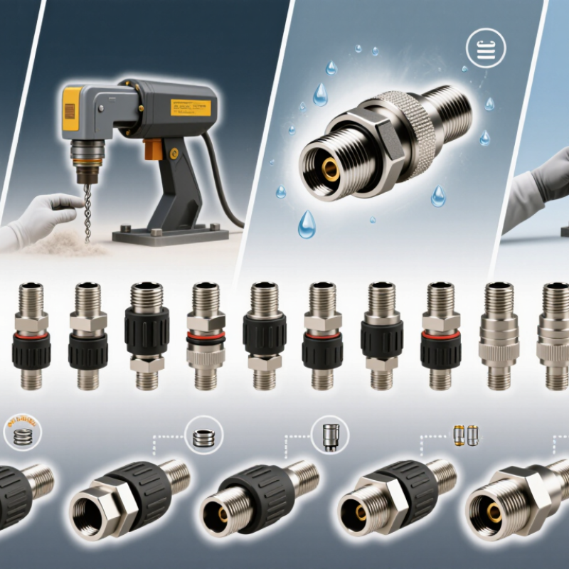
How to Choose a Self Locking Connector

Self-Locking Connectors: Design and Operating Principles

A self-locking connector stays engaged through a mechanical feature, not friction alone. Common designs use a spring-loaded sleeve, latch, or locking ring. During mating, the parts align and the lock moves into place. A small click can help confirm engagement, but sound alone is not proof. Check the connector visually and follow its specified mating procedure.

The locking parts resist accidental separation, while electrical contacts carry current and signal. These functions are related, but they are not interchangeable: a secure latch does not guarantee a sealed or electrically suitable connection. For selection, compare rated current, voltage, contact count, cable size, operating temperature, and exposure to dust or moisture. Also consider vibration, expected mating cycles, and whether technicians can release the lock with gloves. A sleeve that feels firm on a clean workbench may be awkward in a cramped cabinet. Small detail.

A useful check is to test the connector in its actual mounting position, with the intended cable routed as it will be in service. Pull gently on the cable after locking, and inspect for movement or strain at the entry point. Avoid choosing by latch strength alone; housing material, contact plating, and strain relief matter too. Specifications can still leave questions, especially about wear after repeated use. I would verify those limits with test data rather than assume the first satisfying click means the connection is dependable.

Define Application Requirements and Operating Conditions

Before choosing a self-locking connector, define what it must carry and where it will operate. Record the working voltage, current, signal type, and expected load. A power connection and a low-level sensor signal may need very different contact designs. Check the available space, cable diameter, mounting direction, and access for installation. Fit matters.

Operating conditions can change the choice. Note temperature swings, moisture, dust, chemicals, and vibration near motors or moving equipment. A connector used outdoors may need stronger sealing than one inside a clean control cabinet. Consider how often people will connect and disconnect it, too. Frequent servicing can wear contacts and locking features. Check the manufacturer’s ratings against the actual conditions, not just the typical ones. A detail that is easy to overlook is cable strain: a heavy cable can pull sideways on a connector and weaken its hold. It is tempting to focus only on the locking mechanism. That is rarely enough. Confirm that the connector can be handled with gloves, inspected, and released without stressing nearby wiring. If the application is still changing, leave room for a practical fit check; drawings do not always reveal awkward access. Some requirements may conflict. Record the trade-offs before settling on a type.

How to Choose a Self Locking Connector - Define Application Requirements and Operating Conditions
Requirement What to define Why it matters Selection guidance
Application and circuit type Identify whether the connector carries power, signals, data, or a combination, and describe the equipment it connects. Contact layout, insulation, shielding, and connector size depend on the circuit and its function. Choose a configuration with the required number and type of contacts. Keep power and signal requirements distinct when specifying a mixed-contact design.
Voltage and current Specify working voltage, expected current per contact, peak or inrush current, and whether multiple contacts may be loaded at once. Electrical ratings can be affected by contact size, wire size, ambient temperature, and the number of simultaneously loaded contacts. Check the connector’s rated values and derating information under the intended conditions; do not select by nominal current alone.
Signal and data performance Define signal level, frequency or data rate, allowable noise, and any impedance or shielding requirements. Contact arrangement and cable termination can affect signal integrity, electromagnetic compatibility, and crosstalk. For high-speed or noise-sensitive circuits, verify the connector and cable as a complete system, including shielding and grounding details.
Operating temperature Set the minimum and maximum ambient temperatures, including short-term extremes and temperature rise from electrical loading. Temperature can affect contact resistance, insulation properties, seals, and mechanical retention. Confirm that the connector’s rated temperature range covers the actual environment and the expected operating load.
Moisture and contaminants Describe exposure to rain, splashes, immersion, dust, oil, cleaning fluids, salt, or other chemicals. Ingress protection and material compatibility depend on the specific exposure and on whether the connector is mated or unmated. Check the applicable ingress rating and test conditions. Verify sealing requirements for the connector, cable entry, and mated interface together.
Vibration and shock Specify vibration profile, shock exposure, mounting location, and whether the cable can pull or move during operation. A self-locking mechanism helps resist unintended disengagement, but performance also depends on mounting, cable support, and connector design. Use a locking style suited to the expected vibration and service conditions, and provide strain relief so cable loads are not transferred directly to contacts.
Mating frequency and service access Estimate how often the connector will be connected and disconnected, and whether technicians need to operate it with gloves or limited access. Frequent mating can contribute to contact wear, while restricted access can make some locking mechanisms difficult to operate. Check the specified mating-cycle life and assess the release method, grip, visibility, and available clearance in the installed position.
Retention and release Define the required resistance to accidental separation and how intentional disconnection should be performed. Self-locking designs use different engagement and release mechanisms; a secure connection must still be serviceable when needed. Confirm that the connector provides positive engagement and a clear way to verify locking. Consider whether tools or a deliberate release action are acceptable.
Cable and installation constraints Specify conductor size, cable diameter, cable type, bend radius, panel or enclosure space, and mounting method. A compatible termination and suitable cable entry help maintain electrical performance, sealing, and mechanical reliability. Match the connector’s termination range to the cable and allow adequate space for mating, release, and cable routing.
Safety and applicable standards Identify the equipment’s safety requirements, installation location, and any applicable regulatory or industry standards. Voltage, insulation, flammability, touch protection, and environmental requirements vary by application and jurisdiction. Verify ratings and approvals against the actual end-use requirements; connector suitability does not by itself certify the complete equipment.
Maintenance and replacement Define inspection access, expected service life, replacement procedure, and whether field termination is required. Maintainability affects downtime and helps ensure that replacement parts and installation methods preserve the original performance. Document the mating procedure, inspection points, and compatible replacement configuration before finalizing the connector choice.

Compare Locking Mechanisms and Connector Types

How to Choose a Self Locking Connector

Compare Locking Mechanisms and Connector Types

Self-locking connectors differ in how they resist accidental separation. Threaded couplings use a rotating nut to create firm engagement, making them suitable for equipment exposed to sustained vibration. They usually need more time and access to tighten. Bayonet couplings lock with a short twist, which helps when technicians wear gloves or work in tight spaces. Push-pull designs connect quickly, but their release behavior should be checked to prevent snags from pulling them apart. A satisfying click is only a clue, not proof.

Connector shape matters too. Circular types often suit cables routed through compact, enclosed equipment. Rectangular types can simplify dense wiring and multi-contact layouts. Board-to-board connectors save space, but their retention and alignment requirements differ from cable connectors. Compare contact count, current, voltage, sealing needs, mating cycles, and available installation clearance. Then check whether the locking method can be inspected and released safely during maintenance. IEC 60512 provides test methods for evaluating electrical connectors; use the relevant tests and conditions for the application rather than relying on appearance.

The market context shows why careful selection matters, not which lock is best. MarketsandMarkets’ Electrical Connectors Market report estimated a global market value of USD 84.7 billion in 2023 and forecast USD 118.5 billion by 2028, a 7% compound annual growth rate. These figures cover connectors broadly, not self-locking mechanisms specifically. For a real design, compare supplier test data under the expected vibration, temperature, and contamination conditions. A connector that is easy to mate may still be awkward to service. That trade-off is easy to miss.

Evaluate Materials, Ratings, and Compatibility

A self-locking connector should match the job, not just look sturdy. Start with its material and the environment around it. Stainless steel resists corrosion in damp or outdoor settings, while aluminum is lighter but may suit different load conditions. Check for sharp edges, visible wear, and smooth gate movement. Small details matter. A gritty hinge can signal contamination or poor maintenance, even when the body looks sound.

Read the rating carefully. Working load limits and breaking-strength figures are not interchangeable, and dynamic forces can exceed the steady loads people expect. Choose a connector rated for the application, with a suitable safety margin, and follow the maker’s instructions. Check the actual load. I still find ratings easy to skim when comparing products, so I verify the exact figure and what it measures before making a choice. If the documentation is unclear, that uncertainty deserves attention.

Compatibility matters just as much as strength. Compare the connector’s opening, shape, and locking mechanism with the rope, cable, or attachment point it will meet. A narrow gate may not sit properly on a thick eye; a rounded connector can shift against a flat surface. Also consider contact between different metals, since moisture can accelerate corrosion. Test fit the assembly without loading it, then inspect whether the gate closes and locks freely. A connector that is strong on paper may still be the wrong fit.

Inspect, Install, and Test the Selected Connector

How to Choose a Self Locking Connector

Inspect, Install, and Test the Selected Connector

Before installation, inspect the connector under bright light. Check the locking collar, threads, latch, seal, and contact faces for cracks, dents, corrosion, or debris. A lock can feel engaged while damaged threads still allow movement. I’ve found that a quick visual check is easy to rush, so use a flashlight and verify the latch by touch.

Confirm the selected connector’s rated voltage, current, wire size, environment, and mating cycle life against its technical documentation. IEC 60512-9-1 describes mechanical operation endurance testing; its cycle count is a test condition, not a universal service-life guarantee.

Install with power isolated and the cable supported, not hanging from the connector. Align the keying features, seat the halves fully, then engage the lock without forcing it. Stop if the coupling binds. After installation, apply a gentle pull and check that the connector does not separate or rotate.

Test electrical continuity and contact resistance, recording readings in milliohms. IEC 60512-2-1 describes a millivolt-level method for measuring contact resistance; compare results with the connector specification, not an assumed universal limit. Repeat checks after vibration or maintenance. A result that looks acceptable once may still deserve another look. Keep the inspection notes, test conditions, and any unusual fit issues together for the next technician.

SHOP BY BRAND