+1 (281) 855-2218

How to Choose the Right 2510 Connector?

Choosing the right 2510 Connector begins with more than comparing product photos. In many catalogs, “2510” describes a 2.54 mm pitch family, but naming practices can vary between manufacturers. Confirm the datasheet before placing an order. A connector that looks identical may use different terminals, housings, or locking features.

This guide explains how to evaluate a 2510 Connector for real operating conditions. Check the number of positions, rated current, voltage, wire size, insulation material, and contact plating. Consider how the assembly will be installed. A compact board connection may need a vertical header, while a cable harness may require a right-angle version. Vibration, repeated mating, heat, and limited service space also influence the correct choice.

Details matter.

Experienced engineers usually inspect the crimp terminal before approving the housing. Poor crimp compression can create resistance, heating, and intermittent signals. For this reason, verify the recommended crimp height and test sample assemblies under realistic loads. A visual match is not enough. That assumption can fail.

Reliable selection also involves supplier traceability, tolerance information, and documented quality testing. Look for clear drawings, material specifications, and consistent part numbering. If the product will enter a regulated or safety-sensitive system, request applicable certifications and test reports. Standards and ratings should be confirmed for the actual model, not inferred from the series name. A careful comparison may take longer, but it reduces redesigns, field failures, and costly production delays.
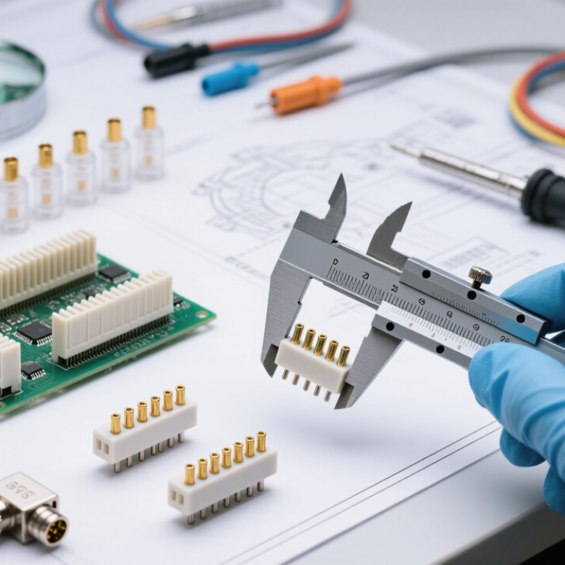
How to Choose the Right 2510 Connector?

Define the 2510 Connector and Its Common Applications

How to Choose the Right 2510 Connector?

Define the 2510 Connector and Its Common Applications

A 2510 connector usually refers to a 2.54 mm pitch wire-to-board connector. Its name comes from the common housing designation, not a universal technical standard. Most versions use a plastic housing, metal crimp terminals, and matching PCB headers. Pin counts vary widely. Orientation may be vertical or right-angle.

These connectors carry low-voltage power and control signals in compact equipment. Typical applications include LED modules, sensors, small control panels, appliances, and embedded circuit boards. They suit prototypes and production assemblies when space and wiring access are limited. Some designs use friction locks. Others rely on a stronger latching structure.

Choosing one requires more than checking pin spacing. Confirm the rated current, voltage, wire size, contact material, and operating temperature. Check whether the terminal accepts solid or stranded wire. Mating direction also matters during installation. A right-angle version can prevent sharp wire bends inside a narrow enclosure.

Inspect the crimp after assembly. It should grip the conductor without cutting the strands. I have seen connectors fit physically but fail under vibration because the terminal was poorly crimped. That detail is easy to underestimate. Review the manufacturer’s drawings and test samples before approval. A connector that looks identical may have different tolerances, plating, or retention strength. Do not assume compatibility from appearance alone.

Identify Electrical, Mechanical, and Environmental Requirements

Choosing a 2510 connector starts with verification, not appearance. In many catalogs, “2510” suggests a 2.54 mm pitch, but naming practices vary. Measure the pitch and confirm the housing drawing. A small mismatch can stop assembly completely.

Define electrical requirements from the actual load. Record continuous current, inrush current, working voltage, wire gauge, and allowable temperature rise. Apply derating instead of using the headline current rating. IEC 60512 testing covers contact resistance, temperature rise, vibration, and durability. These tests provide a stronger basis than a sales-sheet maximum. The 2024 Global Electrical Connectors Market report projects steady market growth through 2030, driven partly by compact industrial equipment. That growth increases the need for repeatable qualification, not guesswork.

Check mechanical details under real installation conditions. Confirm mating cycles, terminal retention, polarization, locking force, PCB tolerance, and cable bend radius. Then examine the environment: operating temperature, humidity, dust, vibration, salt exposure, and flame rating. IP protection should match the enclosure, not the connector alone. UL 94 classifications can support material selection, but they do not replace system-level fire testing. I once focused too heavily on current capacity and overlooked cable strain. The connector passed electrically, yet loosened during vibration testing. That mistake still influences my review checklist.

Compare Contact Count, Pitch, Materials, and Current Ratings

How to Choose the Right 2510 Connector?

A 2510 connector commonly uses a 2.54 mm pitch, but naming conventions can vary. Verify the drawing before ordering. Contact count determines circuit density, cable layout, and assembly time. A six-contact housing may fit a compact control board. A twenty-contact version can reduce wiring space, yet increases inspection difficulty. Leave room for probe access and locking features.

Material selection affects heat, wear, and signal stability. Tin-plated contacts suit many general-purpose circuits. Gold plating offers better resistance to oxidation and repeated mating. Nylon or high-temperature polymer housings can support harsher environments. Do not judge material by appearance. Check temperature ratings, flammability data, and terminal retention force. Small details matter.

Current ratings need careful interpretation. A 2024 electrical connector market analysis by Grand View Research estimated the global market at approximately US$76 billion in 2023. This scale reflects diverse applications, not one universal 2510 rating. Rated current changes with contact size, wire gauge, ambient temperature, and the number of energized contacts. Follow IEC 60512 testing methods and use the supplier’s derating curves. A practical design review should test the connector at expected load, not only its headline rating. I have seen clean calculations fail because adjacent contacts heated each other. That limitation deserves more attention.

Evaluate Connector Compatibility, Installation, and Reliability

How to Choose the Right 2510 Connector?

A 2510 connector should match more than the visible housing size. Check the pitch, pin count, keying direction, and contact layout against the PCB footprint. A connector may fit the board and still fail during mating. Confirm the rated voltage, current, wire size, and operating temperature in the technical documentation. These details matter near motors, heaters, and compact power circuits.

Installation quality strongly affects connector performance. Strip wires to the specified length, then inspect each crimp for proper contact and alignment. Loose crimps create resistance and heat. Too much force can damage the terminal. Keep the cable straight near the housing, and use strain relief where movement is expected. During one assembly review, I focused too much on fit and overlooked cable bending. That shortcut was convenient, but weak.

Reliability requires practical testing, not visual confidence. Check continuity across every circuit, then test for unwanted connections between adjacent contacts. Measure contact retention with a controlled pull test when possible. Repeated mating cycles can reveal latch wear before field installation. Vibration and temperature changes may expose problems that a bench test misses. Document the test conditions and any failed samples. Small connectors deserve careful inspection. They often carry larger consequences than their size suggests.

Select a 2510 Connector Based on Performance and Cost

How to Choose the Right 2510 Connector?

A 2510 connector usually uses a 2.54 mm pitch. Its compact size suits control boards, sensors, and low-voltage wiring. However, price should not lead the selection. A 2024 global connector industry report valued worldwide sales at approximately US$84 billion in 2023. That scale reflects intense cost pressure, but failure costs remain significant. A cheaper housing may increase assembly time, inspection work, and replacement expenses.

Check performance before comparing unit prices. Many 2510 designs list current ratings near 3 A, yet the real limit depends on contact material, wire size, temperature, and mating cycles. Confirm voltage, insulation resistance, contact resistance, and retention force. IEC 60512 test methods provide useful procedures for measuring these characteristics. IPC/WHMA-A-620 also supports consistent cable assembly acceptance. Small details matter.

The first shortlist is rarely perfect. Test samples under vibration, heat, and repeated insertion. Record contact temperature after continuous load. A connector costing two cents less may require stronger crimp tooling or create more rejected assemblies. Include labor, tooling, logistics, and expected service life in the cost model. Choose the lowest total cost that still meets the application’s measured performance, not merely the lowest quotation. Be willing to revise the choice.

How to Choose the Right 2510 Connector? - Select a 2510 Connector Based on Performance and Cost

Selection Factor Standard 2510 Connector Enhanced 2510 Connector High-Reliability 2510 Connector Recommended Choice
Typical pitch 2.54 mm 2.54 mm 2.54 mm Use the same pitch as the PCB header and mating housing.
Common circuit positions 2–20 positions 2–20 positions 2–20 positions Select the lowest position count that meets the wiring requirement.
Typical current rating Up to approximately 3 A per contact Approximately 3–5 A per contact, depending on contact design and wire size Up to approximately 5 A per contact under specified conditions Choose a rating at least 25% above the maximum continuous load.
Typical voltage rating Up to approximately 250 V AC/DC Up to approximately 250 V AC/DC Up to approximately 250 V AC/DC, subject to creepage and clearance requirements Verify the certified voltage rating for the final insulation system.
Compatible wire range Commonly 22–28 AWG Commonly 20–26 AWG Commonly 20–26 AWG, depending on the terminal Match the terminal crimp range to the actual conductor size.
Contact resistance Typically below 20 mΩ initially Typically below 20 mΩ initially Typically below 10–20 mΩ initially, with improved retention after cycling Use the lowest verified value when voltage drop and heating are critical.
Operating temperature Approximately −25°C to +85°C Approximately −40°C to +105°C Approximately −40°C to +125°C, if high-temperature materials are specified Select a range covering the full ambient temperature plus self-heating.
Mating protection Basic friction retention Positive locking feature Positive lock with stronger terminal retention Use a locking design where vibration, movement, or repeated service is expected.
Insulation material General-purpose thermoplastic Temperature-rated thermoplastic High-temperature, flame-retardant thermoplastic Choose the material according to temperature, flammability, and regulatory requirements.
Contact material Tin-plated copper alloy Tin-plated copper alloy with improved spring design Higher-retention copper alloy contact, sometimes with selective plating Tin plating is generally cost-effective; select upgraded plating for harsh or low-level signal environments.
Approximate relative cost 1.00× baseline Approximately 1.15–1.40× baseline Approximately 1.40–2.00× baseline Compare total cost, including crimping, testing, replacement, and downtime.
Best-fit application Indoor control panels, consumer equipment, and cost-sensitive assemblies Industrial controls, automotive interior electronics, and equipment exposed to moderate vibration High-temperature equipment, high-vibration systems, and applications requiring maximum retention Base the final selection on load, environment, service life, and compliance requirements.

Note: The values above are typical engineering ranges for 2.54 mm-pitch 2510-style connectors. Actual ratings depend on the terminal design, wire size, contact spacing, temperature rise, mating parts, and applicable safety standards. Always confirm the final values in the product-specific datasheet.

Article Source:

SHOP BY BRAND