Main Menu
Choosing the right Grounding Accessories is a safety decision, not merely a purchasing task. Clamps, bonding jumpers, earth rods, connectors, and inspection points must work as one reliable path. A loose clamp may look harmless during installation. Under fault current, it can become a serious weakness.
NFPA’s report, Home Structure Fires Started by Electrical Distribution and Lighting Equipment, estimated about 35,150 U.S. home fires annually from 2012 to 2016. These incidents caused approximately $1.3 billion in direct property damage each year. The report does not blame grounding accessories alone, but it shows why connection quality deserves careful attention. Small parts matter.
Professional selection should follow the installation environment and the applicable engineering standard. IEC 60364-5-54 addresses protective conductors, earthing arrangements, and equipotential bonding. IEEE Std 80 provides guidance for grounding safety in substations, including touch and step voltage considerations. NFPA 70, the National Electrical Code, also provides widely used requirements for grounding and bonding in the United States. These standards support decisions based on fault current, soil conditions, corrosion exposure, conductor size, and mechanical strength.
In practical work, a copper-clad ground rod may suit one soil condition but perform poorly where corrosion or rocky ground dominates. Bimetallic connectors can help prevent unsuitable metal contact. Inspection wells should remain accessible, even after landscaping changes. Yet no accessory can correct an undersized conductor or poor design. That point is easy to miss. Product labels alone are not enough. A dependable choice combines verified test data, compatible materials, qualified installation, and periodic inspection. Some projects still rely too heavily on habit. Rechecking that habit is worthwhile.
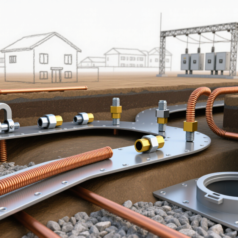
Grounding accessories are not minor hardware. They create a controlled path for fault current, helping protective devices disconnect power before a metal enclosure becomes dangerous. In practical inspections, loose lugs, painted contact surfaces, and mismatched clamps often cause more concern than the grounding conductor itself. Choose accessories rated for the conductor material, fault current, temperature, moisture, and installation environment. Copper and aluminum connections need compatible terminals and approved anti-oxidation measures where required. Outdoor systems may need corrosion-resistant clamps and sealed connections. Check the installation instructions carefully.
The risk is measurable. NFPA’s Electrical Fires Involving Home Electrical Distribution and Lighting Equipment report estimated about 32,000 home fires annually from 2015 to 2019, causing roughly 470 deaths and 1,100 injuries. Grounding cannot prevent every electrical fire, but it can reduce shock exposure and support overcurrent protection. OSHA 29 CFR 1910.304 and IEC 60364 also emphasize effective grounding and bonding arrangements. Verify continuity with suitable test equipment, not visual inspection alone. It is easy to overtrust a clean-looking connection. That is a mistake. A qualified electrician should confirm conductor sizing, bonding points, electrode performance, and local code compliance before energizing the circuit. Field conditions can be less perfect than drawings.
Protective conductors, grounding clamps, bonding jumpers, earth bars, and test links must be selected to safely carry fault current and maintain a continuous low-impedance path to earth. The chart shows simplified minimum copper protective-conductor areas based on the IEC 60364-5-54 table method, assuming the protective conductor is made from the same material as the phase conductor.
For conductors up to 16 mm², the protective conductor is sized equal to the phase conductor. Between 16 and 35 mm², 16 mm² is used; above 35 mm², the protective conductor is typically at least half the phase-conductor area. Final selection must also consider local regulations, fault current, disconnection time, mechanical protection, corrosion resistance, and the compatibility of clamps and terminals.
Choosing grounding accessories begins with the site, not a catalog. I have inspected installations where dry, rocky soil made a standard rod ineffective. Measure soil resistivity at several points and seasons when practical. Note groundwater, drainage paths, buried services, and available installation depth. A clamp that works in mild soil may fail quickly near fertilizer, salt, or industrial chemicals. Look closely.
The grounding system requirement comes next. Confirm the expected fault current, disconnection time, touch-voltage limits, and conductor size. Select rods, tapes, bonds, inspection pits, and connectors as one coordinated path. Every joint must carry fault current safely and resist loosening, moisture, and corrosion. In wet ground, corrosion-resistant materials may be necessary, but material compatibility still matters. Dissimilar metals can create galvanic corrosion. A qualified electrical engineer should verify calculations and local code requirements. Field judgment helps, but it cannot replace testing.
During installation, check that connectors are fully seated and accessible for inspection. Photograph hidden joints before backfilling. Then test continuity and earth resistance using suitable instruments. Do not rely on a single reading. Soil conditions change. I once treated a low initial resistance as proof of success, yet later testing exposed a poor bond after seasonal drying. That mistake reinforced a simple lesson: accessories should match measured conditions, maintenance plans, and the system’s real fault path. Leave room to improve the design when evidence changes.
Grounding accessories should be selected as one connected system, not as isolated parts. Start with the grounding conductor. Its size depends on fault current, circuit protection, installation method, and local electrical requirements. Copper offers excellent conductivity and flexibility. Aluminum can reduce weight, but requires careful control of oxidation and joint compatibility.
OSHA reports approximately 300 electrical deaths and 4,000 electrical injuries annually in the United States. Reliable grounding reduces risk, but it cannot replace inspection or safe work practices.
Ground rods must match soil conditions, moisture, and required resistance. The IEEE 142 grounding guide emphasizes soil resistivity testing before designing electrode systems. A longer rod is not always better. Multiple electrodes may perform better in rocky or dry soil.
Use listed clamps that resist loosening, corrosion, and mechanical damage. Connectors should match the conductor material and remain accessible for testing. IEC 60364-5-54 also stresses durable protective bonding and suitable earthing arrangements. I have seen installations fail because a clean-looking clamp hid corrosion underneath.
Tips:
Check soil resistivity before choosing rods. Keep dissimilar metals separated unless the connector is approved for them. Tighten connections with calibrated tools. Photograph buried joints before backfilling. Test continuity after installation, then record the readings. A single good reading can mislead. Seasonal soil changes matter. Review the design when conditions change.
How to Choose the Right Grounding Accessories?
Grounding accessories should match the conductor, equipment, and installation environment. Start by checking material compatibility. Copper, aluminum, galvanized steel, and stainless steel can react differently when joined. Moisture and salt air may accelerate corrosion. A compatible connector should maintain low electrical resistance over time. Do not judge compatibility by appearance alone.
Ratings require equal attention. Check the accessory’s current capacity, voltage rating, short-circuit withstand, and temperature range. A clamp installed outdoors may face ultraviolet exposure, rain, vibration, and freezing conditions. Confirm that its size range fits the conductor without forcing or excessive looseness. Small details matter. A poor fit can create heat at the connection point.
Safety standards provide a reliable reference, but they are not a substitute for inspection. Look for documented compliance with applicable IEC, UL, or national electrical requirements. Verify test reports, installation instructions, and traceable material information. The grounding path should remain continuous after tightening, movement, and environmental stress. A torque wrench is useful here. Hand-tight may feel secure, yet it can be inadequate. I have found that checklists sometimes create false confidence; they can miss damaged threads, contamination, or an incorrect washer. Recheck the connection after installation, especially where equipment vibrates. When conditions are uncertain, consult a qualified electrical professional rather than guessing.
| Accessory Type | Typical Application | Common Materials | Material Compatibility Check | Rating or Selection Basis | Relevant Standards | Key Safety Checks |
|---|---|---|---|---|---|---|
| Ground Rod Clamp | Connecting a grounding conductor to a driven earth rod. | Copper alloy, bronze, tinned copper, or stainless steel. | Select a clamp listed for the rod and conductor materials. Avoid unprotected direct contact between dissimilar metals where moisture is present. | Conductor size range, rod diameter range, fault-current duty, and environmental exposure. Do not use a clamp outside its marked range. | UL 467; IEC 62561-1 where used in a lightning protection system. | Ensure full conductor insertion, correct tightening, mechanical protection, and accessibility for inspection where required. |
| Mechanical Cable Connector | Joining grounding conductors or connecting a conductor to a grounding bar. | Copper, tinned copper, bronze, brass, or stainless steel. | Use connectors specifically approved for copper-to-copper, copper-to-aluminum, or other specified combinations. Copper-to-aluminum connections generally require a listed bimetallic design. | Conductor cross-sectional area, number of conductors, short-circuit current, installation method, and corrosion conditions. | UL 467; IEC 62561-1; IEC 60364-5-54 for electrical installations. | Follow the specified torque, keep contact surfaces clean, and prevent strand damage during installation. |
| Exothermic Weld Connection | Permanent connections between grounding conductors, rods, structural steel, or buried conductors. | Usually copper conductors, copper-coated steel, galvanized steel, or compatible stainless-steel components. | The mold and welding material must be designed for the exact conductor and electrode combination. Confirm compatibility with coated or galvanized surfaces. | Connection geometry, conductor size, electrode type, fault-current duty, and permanent burial requirements. | IEC 62561-1; project specifications and applicable electrical installation requirements. | Use trained personnel, dry molds, correct charge size, eye and heat protection, and adequate ventilation. |
| Earth Electrode | Dissipating fault or lightning current into the soil. | Copper, copper-bonded steel, galvanized steel, or stainless steel. | Match the electrode coating and connector material. Consider soil chemistry, moisture, chloride content, and galvanic corrosion risk. | Length, diameter, material, coating thickness where applicable, soil resistivity, and required grounding resistance or touch-voltage performance. | IEC 62561-2; IEEE 80; IEC 60364-5-54; local electrical codes. | Verify burial depth, separation from buried services, mechanical protection, corrosion allowance, and test access. |
| Grounding Conductor | Bonding equipment, structures, enclosures, electrodes, and grounding bars. | Bare copper, insulated copper, aluminum, galvanized steel, or copper-clad steel. | Use terminals and connectors approved for the conductor metal. Protect aluminum from unsuitable soil and moisture conditions. | Ampacity or short-circuit withstand, minimum code size, mechanical robustness, and expected fault duration. | IEC 60364-5-54; IEEE 80; applicable national wiring regulations. | Provide continuous bonding, avoid sharp bends, protect against physical damage, and identify the conductor according to local code. |
| Grounding Bar or Earth Terminal Bar | Central termination point for protective, bonding, and grounding conductors. | Copper, tinned copper, aluminum, or copper-plated steel. | Check compatibility between the bar, lugs, fasteners, and conductors. Use plated hardware or approved interface compounds where specified. | Bar cross-section, number of terminals, conductor size range, short-circuit withstand, and enclosure environment. | IEC 60364-5-54; UL 467 where applicable; equipment and panelboard standards. | Maintain clear labeling, provide adequate creepage and clearance, and prevent loose or duplicated terminations. |
| Bonding Jumper | Bonding doors, removable panels, cable trays, pipes, and structural sections. | Flexible tinned copper braid, stranded copper cable, or approved aluminum conductor. | Use compatible lugs and fasteners. Tinned copper is often preferred in humid or corrosive environments, subject to the installation specification. | Required fault-current capacity, length, flexibility, vibration resistance, and minimum cross-sectional area. | IEC 60364-5-54; applicable equipment and machinery standards. | Keep the jumper short, avoid relying on hinges or painted joints, and ensure secure terminations at both ends. |
| Lightning Protection Connector | Connecting air-termination conductors, down conductors, and earth termination components. | Copper, tinned copper, aluminum, stainless steel, or compatible copper alloys. | Do not combine incompatible metals without a listed transition component. Verify the connector is intended for the conductor material and exposure conditions. | Lightning-current capability, conductor dimensions, installation location, mechanical strength, and corrosion resistance. | IEC 62561-1; IEC 62305 series; NFPA 780 where applicable. | Maintain the designed separation distance from other conductive systems and ensure low-impedance, mechanically secure connections. |
| Inspection Pit or Test Box | Providing access to an earth electrode connection for inspection and testing. | Polymer concrete, fiberglass-reinforced polymer, plastic, concrete, or metal with corrosion protection. | The enclosure should withstand soil moisture, ultraviolet exposure, traffic loads, and chemical conditions appropriate to its location. | Load class, internal dimensions, water resistance, drainage, cover security, and access requirements. | Project requirements, local civil standards, IEC 62561 system requirements where applicable. | Keep the connection accessible, prevent standing water where possible, and protect the test joint from accidental damage. |
| Ground Enhancement Material | Improving contact between an electrode and high-resistivity soil where permitted by the design. | Conductive concrete, bentonite, graphite-based compounds, or other engineered backfill materials. | Confirm that the material is non-corrosive to the electrode and does not create harmful chemical or environmental effects. | Soil resistivity, moisture retention, leaching behavior, service life, and required grounding performance. | Project specifications; IEC 60364-5-54 and local environmental requirements. | Use only where approved by the design authority, install according to the material instructions, and verify long-term performance. |
Note: Current ratings, fault-current withstand, conductor sizes, tightening torques, and installation details must be confirmed from the applicable product certification, design calculation, and local electrical code.
Choosing grounding accessories starts with the installation environment. Soil moisture, corrosion, fault current, and conductor size all matter. Use listed clamps, lugs, bonding jumpers, test links, and earth electrodes suited to the system. IEC 60364 emphasizes reliable protective bonding and continuity throughout the installation. A small, loose connection can become a dangerous heating point.
Installation quality is only the beginning. Before energizing equipment, technicians should inspect contact surfaces, tighten connections to the specified torque, and verify conductor continuity. IEEE Standard 81 provides methods for measuring earth resistance and soil resistivity. In practice, a three-point or fall-of-potential test can reveal problems that visual checks miss.
Record test locations, weather, instrument settings, and measured values. Keep the evidence.
Testing should follow the equipment risk and maintenance schedule. The National Fire Protection Association’s electrical safety guidance supports documented maintenance programs, while Electrical Safety Foundation reports have recorded more than 100 workplace electrical fatalities in several recent U.S. years.
Grounding is not a paperwork exercise. I have seen clean-looking terminations fail after moisture entered a poorly sealed enclosure. That mistake is easy to underestimate. Retest after modifications, flooding, lightning, or abnormal fault events. Trends matter more than one perfect reading, and my own preference is to question unusually stable results rather than trust them blindly.
Office: (281) 855-2218
Copyright © 2025 Telco Intercontinental Corp. All rights reserved. Privacy Policy | Legal Disclaimer
Telco®, TelcoMotion®, and TelcoGreen® are registered trademarks of Telco Intercontinental Corp.