+1 (281) 855-2218

What Is a FOC Motor Controller and How Does It Work?

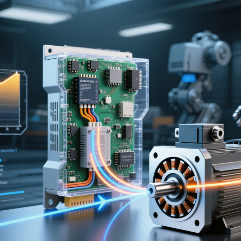
A Foc Motor Controller uses field-oriented control to regulate a motor’s magnetic field and torque. Instead of switching motor phases in a simple sequence, it coordinates their currents as a rotating electrical vector. This approach can make a motor quieter and smoother, especially at low speeds. It is commonly used with permanent-magnet synchronous motors and brushless AC motors in robotics, electric vehicles, and industrial equipment.

Inside the controller, sensors or estimation algorithms track the rotor’s position. The controller transforms measured phase currents into two components: one associated with magnetic flux, and another with torque. It then adjusts these currents and sends switching commands to an inverter, which supplies carefully timed power to the motor. Fast feedback matters. A poorly tuned system can feel jerky, run hot, or respond slowly, even when its hardware is capable.

The details vary. Some systems use encoders or Hall sensors; others estimate rotor position from electrical signals. Sensorless control can reduce hardware, but may be less reliable at very low speeds. That trade-off is easy to overlook. This guide explains what a Foc Motor Controller does, how its control loop works, and which design choices affect performance. Real results depend on motor characteristics, current sensing, software tuning, and operating conditions—not just the controller’s label.
What Is a FOC Motor Controller and How Does It Work?

FOC Fundamentals: Regulating Motor Torque and Flux in the d–q Frame

A field-oriented control (FOC) controller separates motor current into two components using the rotating d–q reference frame. The d-axis current controls magnetic flux; the q-axis current produces torque. A controller measures phase currents, estimates rotor position, then transforms the readings into this frame. It adjusts each current through feedback loops and sends switching commands to the inverter. The math looks clean. Real motors are less tidy.

For a surface-mounted permanent-magnet motor, designers often target near-zero d-axis current below base speed, directing more current toward torque. At higher speeds, negative d-axis current can weaken the effective field and extend the operating range. This balance depends on motor parameters, temperature, and current limits. IEA’s 2011 report, Energy-Efficiency Policy Opportunities for Electric Motor-Driven Systems, estimated that motor-driven systems use about 45% of global electricity. That scale makes efficient control valuable, but FOC alone cannot guarantee efficiency; tuning and system design matter.

Tips: Check current-sensor offsets before tuning the d–q loops. A small offset can create unwanted torque ripple. Confirm rotor-angle estimates under changing loads, too. One detail is easy to overlook: a neat simulation may not capture real sensor noise.

FOC Motor Control: Regulating Torque and Flux in the d–q Frame

In field-oriented control, the d-axis current primarily controls flux, while the q-axis current controls torque. This example shows a q-axis current command stepping from 4 A to 12 A and the measured current tracking it, while d-axis current stays near its 0 A reference—a common strategy for a surface-mounted permanent-magnet motor below base speed.

Feedback Inputs: Measuring 3-Phase Currents and Rotor Position

A field-oriented control (FOC) motor controller uses feedback to regulate torque and speed smoothly. It measures three-phase currents and senses or estimates the rotor’s position. These signals show how the motor’s magnetic field relates to the rotor. Small errors matter. Noise matters too.

Current sensors may measure phase currents directly or use the inverter’s DC link to reconstruct them. The controller samples these readings in sync with switching. An encoder or resolver can provide rotor angle, while sensorless control estimates it from electrical behavior. That estimate can be less certain at very low speed. Using the current and angle data, the controller calculates torque-producing and flux-producing components, then adjusts the inverter’s switching. Poor readings can cause uneven torque, extra heat, or rough operation.

Tips: Check current-sensor offsets while the motor is stopped. Compare position feedback during a slow, unloaded rotation before adding load. Keep sensor wiring secure, and inspect readings under real operating conditions. Bench results can be misleading; verify the setup more than once.

Coordinate Transforms: Converting Phase Currents with Clarke and Park

A field-oriented control (FOC) motor controller uses Clarke and Park transforms to make three-phase current easier to control. The Clarke transform converts measured phase currents, often labeled ia, ib, and ic, into stationary alpha-beta components. For a balanced motor, the three currents sum to approximately zero, so the controller can derive the third from the other two. The Park transform then rotates alpha-beta values using the rotor’s electrical angle, producing d-q currents. The d-axis relates mainly to magnetic flux; the q-axis relates mainly to torque. The math is compact. The angle matters.

In practice, the controller compares measured d-q currents with target values, then adjusts inverter switching to reduce the error. A delayed angle estimate, noisy current samples, or sensor offsets can make the axes interact, so neat equations do not guarantee smooth torque.

The International Energy Agency’s 2011 report, Energy-Efficiency Policy Opportunities for Electric Motor-Driven Systems, estimated that motor-driven systems accounted for about 46% of global electricity use. That figure describes motor-driven systems overall, not savings from FOC. Still, it shows why precise motor control matters.

A useful bench check is to watch whether q-axis current rises cleanly when torque demand increases. Real waveforms can be messier.

Current Control: PI Regulators Set d–q Voltages for Each Control Cycle

In a field-oriented control (FOC) drive, the current loop turns measured phase currents into two useful quantities: d-axis current and q-axis current. A rotor-position estimate supplies the electrical angle for this transformation. The d-axis channel usually manages magnetic flux, while the q-axis channel produces torque. Their target values are compared with measured values every control cycle. The errors feed separate proportional–integral (PI) regulators. Each regulator adjusts its output to reduce the mismatch. This is the fast inner loop, often running much faster than the speed loop. Small errors matter.

The PI outputs become commanded d–q voltages, not direct motor currents. A controller may add decoupling terms for cross-coupling and back electromotive force. It then limits voltage to what the DC bus can provide. Anti-windup logic helps keep the integrators from building up error during voltage saturation. The voltage commands are transformed back into three-phase values, and modulation produces inverter switching commands. On a test bench, a sudden torque request can reveal a sluggish q-axis response or noisy current feedback. Tuning gains is not just a math exercise. Sampling delay, motor inductance, and sensor noise all affect the result. A compromise remains, and it needs checking under real load.

Inverter Output: Six Switches Generate 3-Phase PWM at Typically 10–40 kHz

A field-oriented control (FOC) drive turns its calculated voltage commands into three-phase power through a six-switch inverter. Each motor phase connects to a pair of switches: one links it to the positive DC bus, the other to the negative bus. The controller rapidly changes their on-and-off timing, creating pulse-width-modulated outputs. The motor’s inductance smooths these pulses into usable phase currents.

A carrier frequency of 10–40 kHz means thousands of switching cycles each second. At 20 kHz, the pulse pattern repeats 20,000 times per second; changing pulse width adjusts the average voltage delivered to each phase. The U.S. Department of Energy’s 2021 U.S. DRIVE Electrical and Electronics Technical Team Roadmap sets a 98% peak-efficiency target for traction inverters. It is a target, not a promise of real-world performance. Faster switching can reduce current ripple, but it also raises switching losses and heat. Dead time between paired switches prevents both from conducting together. That brief pause can distort the output slightly. The trade-off is not perfectly tidy: the best frequency depends on motor inductance, power level, and cooling.

SHOP BY BRAND