Main Menu
Choosing the right Bms Wire Harness is not a cosmetic decision. It directly affects battery safety, monitoring accuracy, assembly time, and long-term reliability. A harness connects cells, sensors, balancing circuits, and the battery management system. One incorrect wire length or terminal position can create serious troubleshooting problems.
In practical battery projects, I have seen neat-looking harnesses fail because their wire gauges were selected too casually. Current capacity, insulation temperature, connector locking force, and voltage-drop performance all deserve careful review. The harness should match the battery pack’s operating current, cell arrangement, enclosure space, and expected vibration. Small details matter. A loose crimp can heat under load.
Signal wires also require attention. Temperature-sensor and voltage-sensing lines should be routed carefully, away from unnecessary electrical noise and sharp metal edges. Labels, color coding, and clear pin assignments make production checks easier. However, color alone is not enough. Always verify the pinout against the BMS manufacturer’s technical documentation.
A reliable selection process includes sample inspection, continuity testing, insulation checks, pull testing, and a realistic trial installation. Test it physically. The perfect drawing may not fit the actual pack. This is where many teams need to reflect: speed during purchasing can create delays during assembly. Choosing a qualified supplier with traceable materials, controlled crimping, and documented quality procedures offers stronger confidence. The best Bms Wire Harness is not simply the cheapest or most attractive option. It is the one that fits accurately, carries current safely, protects sensitive signals, and performs consistently in real battery conditions.
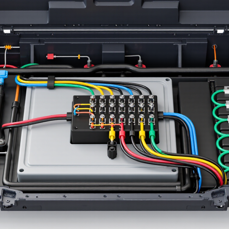
Choosing the right BMS wire harness starts with measurable requirements, not connector appearance. Define the system voltage range, from 12 V to 800 V, before selecting insulation and spacing. At higher voltages, creepage, clearance, and insulation ratings become critical. A harness suitable for a small battery may fail badly in a high-voltage pack.
Count every series-connected cell or module carefully. The BMS must receive one accurate voltage signal per monitoring point. Missing one connection can distort the entire protection strategy. Cell count also determines harness length and the number of sensing wires. Keep these wires separated from high-current paths where possible. Small errors matter.
Current requirements need equal attention. Measure continuous current, peak current, and expected overload duration. Temperature conditions should include normal operation, charging, storage, and cold starts. Place temperature sensors near cells, busbars, and likely heat sources. In practical battery assembly, loose crimping often creates resistance and heat. It looks minor at first. It is not.
Use wire gauges based on current, distance, and allowable voltage drop. Check connector locking strength and terminal retention during vibration. Include clear labels for every sensing lead. I have seen installation teams reverse two similar wires during rushed testing. Better labeling would have prevented the problem. A final continuity, insulation, polarity, and temperature-sensor test should be recorded before energizing the pack.
How to Choose the Right BMS Wire Harness?
Size conductors by ampacity, voltage drop, and a 10–20% safety margin. A 30 A continuous load therefore needs at least 33–36 A capacity. NFPA 70 (2023), Table 310.16, lists 14 AWG copper at 25 A and 12 AWG at 30 A under a 90°C rating. However, that table is not an automotive harness design. Bundling, enclosure temperature, insulation limits, and connector ratings can reduce real ampacity. IEC 60287-1-1:2023 also bases cable capacity on conductor resistance, heat generation, and thermal conditions.
Voltage drop deserves equal attention. Use V = IρL/A, with the full circuit length included. For example, 5 A through a two-metre loop of 1.5 mm² copper creates roughly 0.12 V drop at 20°C. Higher temperature increases resistance. Keep high-current paths short, and verify the worst-case drop at low battery voltage. A 10% margin may be reasonable for a cool, open harness. A cramped battery enclosure may justify 20%. The margin is not magic.
Tips: Confirm the continuous current, peak current, and fault-clearing time separately. Check crimp resistance, not only cable size. Measure the warmest bundle after a realistic load test. I still recheck calculations manually; spreadsheets can hide wrong cable lengths. BMS sense wires need careful routing, strain relief, and shielding from noisy power conductors. A thicker wire cannot repair a poor terminal.
Choosing the right BMS wire harness begins with insulation, not connector appearance. For automotive packs, specify insulation that remains stable from −40°C to 125°C. That range covers cold starts, engine-bay heat, and repeated thermal cycling. Do not treat 125°C as an automatic operating target. Ask whether it is continuous, intermittent, or measured near a heat source. This distinction matters.
Common insulation options include cross-linked polyolefin, ETFE, and silicone. Each behaves differently under abrasion, chemicals, bending, and compression. Cross-linked materials offer balanced mechanical protection for many battery assemblies. ETFE can suit compact, demanding routes where thin walls and chemical resistance matter. Silicone stays flexible in severe cold, but its softer surface needs careful routing. A thin jacket is not always better.
During design reviews, inspect the harness beside busbars, cooling plates, and sharp brackets. Leave room for expansion and secure the cable without crushing the insulation. Test samples through cold-soak, heat-aging, vibration, and repeated bend cycles. Check stripped sections too; failures often begin where insulation meets a terminal. Use supplier data, then verify it on the actual pack geometry. I would not rely on a datasheet alone. One overlooked clamp can defeat excellent material selection. Recheck assumptions after every prototype change.
How to Choose the Right BMS Wire Harness?
Specify connectors for 2–500 A by separating signal, continuous-current, and peak-current duties. A 2 A sensing circuit needs low noise and stable locking. A 500 A path needs busbar support, low contact resistance, and thermal derating. The IEA Global EV Outlook 2024 reported more than 14 million electric cars sold globally in 2023. That growth increases pressure on battery harness reliability. Do not trust nominal current alone. Check conductor temperature, enclosure temperature, duty cycle, and voltage drop together.
Vibration can loosen an acceptable connector. ISO 16750-3 provides useful guidance for mechanical loads in road vehicles. Specify secondary locks, strain relief, and terminals that resist fretting. Sealing also needs a defined target. IEC 60529 IP ratings describe protection against dust and water, but IP67 does not guarantee long-term chemical resistance. Test the actual harness with coolant exposure, pressure washing, and temperature cycling. This is where many clean datasheets become less convincing.
For high-voltage packs, the HV interlock loop should use dedicated low-current contacts. The system must detect an open connector before dangerous power is enabled. Include touch-safe geometry, clear polarization, and a CPA or TPA feature. I would avoid selecting a connector from current rating alone. Real assemblies often fail at bends, seals, or poorly supported exits. A few extra millimeters of service loop may prevent a costly field issue. That detail is easy to overlook.
Typical continuous-current design points for BMS and battery-pack harness sections. Connector selection must also verify voltage rating, temperature rise, vibration resistance, sealing, creepage, clearance, and HVIL compatibility.
Low-current sensing and balancing circuits commonly use small signal connectors, while contactor, module-link, and pack-output circuits require larger power terminals. The values shown are representative engineering ranges rather than universal connector ratings; final selection should include application-specific derating and fault-current analysis.
How to Choose the Right BMS Wire Harness?
A BMS wire harness must do more than connect cells and sensors. It must preserve signal accuracy under vibration, heat, moisture, and repeated service. Start by checking insulation ratings, conductor size, terminal retention, bend radius, and shielding needs. These details affect voltage readings and fault detection.
Validate the harness through the ISO 26262 safety lifecycle. ISO 26262 does not certify a harness alone. It helps teams identify hazards, define safety goals, and trace verification evidence. Review crimp quality, insulation resistance, short-circuit protection, and diagnostic coverage. Use LV 214 testing to assess connector performance, including mechanical strength, contact resistance, vibration, and environmental durability. Requirements should match the vehicle’s actual conditions, not only laboratory assumptions.
Tips: Run at least 1,000 mating and unmating cycles when service access requires repeated connection. Measure contact resistance during testing, not only at the end. Record small changes. A connector may still function while its resistance slowly increases. Include temperature cycling and vibration together, because real failures rarely appear in isolation. No test plan is flawless. Teams sometimes overfocus on the connector and overlook routing near hot surfaces or sharp brackets. A final review should examine photographs, test data, and installation samples. That practical step often reveals clearance problems that drawings miss.
| Validation Area | What to Define Before Selection | Recommended Engineering Data | Validation Method | Acceptance Criteria / Evidence |
|---|---|---|---|---|
| Electrical Architecture | Number of cells, sensing channels, balancing circuits, service loops, and auxiliary power lines. | Cell-monitoring circuits commonly use low-current measurement conductors, while balancing circuits may carry approximately 50–300 mA depending on the BMS design. | Review the wiring diagram, pinout, connector keying, and circuit separation. | Pass Every circuit has a defined function, pin assignment, protection strategy, and diagnostic path. |
| Conductor Selection | Current, allowable voltage drop, conductor length, temperature, insulation system, and routing conditions. | Use the conductor cross-sectional area and insulation rating calculated for the actual load and environment. For a 1.5 m one-way copper circuit, remember that voltage-drop calculations use approximately 3.0 m of total circuit length. | Perform resistance, voltage-drop, and thermal calculations at the maximum continuous and peak load. | Pass Voltage drop and conductor temperature remain within the project limits at the worst-case operating condition. |
| Signal Integrity | Measurement accuracy, noise exposure, shielding requirements, and separation from high-current switching paths. | Keep cell-sense wires twisted or routed consistently where required, minimize unintentional loop area, and separate sensitive measurement lines from high-current conductors. | Check resistance balance, continuity, induced-noise susceptibility, and measurement deviation under switching loads. | Pass No intermittent open circuit, unacceptable measurement offset, or communication disturbance is observed. |
| Crimp and Terminal Quality | Terminal size, wire gauge range, crimp geometry, pull-out strength, and contact resistance. | Crimp dimensions and pull-force limits must come from the selected terminal and wire combination; they are not universal values. | Use crimp-height inspection, cross-section analysis, terminal pull testing, and millivolt-drop measurement. | Pass Crimps meet the terminal supplier's validated specification, with no broken strands, bell-mouth defect, or excessive contact resistance. |
| ISO 26262 Alignment | Safety goals, ASIL allocation, fault reactions, and the harness contribution to the safety concept. | Analyze harness faults such as open circuit, short to ground, short between adjacent circuits, reversed connection, and increased contact resistance. | Document the harness interface in the HARA, functional safety concept, technical safety concept, and safety analysis as applicable. | Pass Safety-related faults have defined detection, mitigation, or controlled-failure behavior. ISO 26262 does not independently certify a wire harness. |
| LV 214 Interface Validation | Connector mating, terminal retention, mechanical loading, electrical performance, and environmental exposure. | LV 214 is commonly used as an automotive connector testing reference; exact severities and acceptance limits depend on the connector and project specification. | Apply the relevant LV 214-based sequence for contact resistance, vibration, temperature cycling, humidity, mechanical abuse, and terminal retention. | Pass The connector remains mated, terminals remain retained, and electrical performance stays within the approved component specification. |
| Mating Durability | Serviceability requirements, connector access, latch design, and expected maintenance events. | Automotive connector mating ratings vary by design; 1,000 mating cycles should be treated as a demanding, project-defined durability target rather than a universal LV 214 requirement. | Mate and unmate the complete harness assembly for 1,000 cycles using controlled alignment, speed, and insertion force. | Pass No latch failure, terminal back-out, seal damage, abnormal insertion-force increase, or unacceptable contact-resistance rise occurs. |
| Environmental Durability | Temperature range, humidity, condensation, salt exposure, fluids, vibration, and mechanical strain. | Define the vehicle installation zone and use the applicable environmental profile; a typical development envelope may include approximately −40°C to +125°C, subject to the vehicle design. | Combine temperature cycling, damp heat, vibration, fluid exposure, and post-test electrical inspection. | Pass No insulation cracking, seal leakage, corrosion that affects function, chafing, or intermittent electrical fault is detected. |
| Insulation and Isolation | Insulation material, creepage, clearance, dielectric withstand, and isolation-monitoring strategy. | Test voltage and insulation-resistance limits must be specified by the battery-pack electrical architecture and applicable component requirements. | Perform continuity, insulation resistance, dielectric withstand where applicable, and isolation checks before and after environmental tests. | Pass Measured values remain above the project-defined minimum, with no dielectric breakdown or unintended conduction path. |
| Mechanical Routing | Bend radius, clamp spacing, abrasion points, connector strain relief, and tolerance stack-up. | Maintain the cable manufacturer's minimum bend radius and prevent the connector from carrying continuous wire tension or sharp-edge contact. | Inspect the installed routing and conduct vibration, flex, abrasion, and pull-strain testing under representative assembly conditions. | Pass No conductor fatigue, terminal movement, insulation wear-through, clip release, or connector load-transfer failure is found. |
| Production Traceability | Crimp tooling, inspection frequency, test coverage, repair controls, and end-of-line verification. | Record wire batch, terminal lot, tooling identification, crimp measurements, continuity results, and operator or machine traceability. | Use 100% continuity and short-circuit testing, supported by periodic crimp cross-sections and pull-force audits. | Pass Each harness has a retrievable quality record and no unapproved splice, terminal, wire, or repair is present. |
Office: (281) 855-2218
Copyright © 2025 Telco Intercontinental Corp. All rights reserved. Privacy Policy | Legal Disclaimer
Telco®, TelcoMotion®, and TelcoGreen® are registered trademarks of Telco Intercontinental Corp.