
Main Menu

Solar power is scaling quickly, and every module depends on a frame that holds its position through wind, rain, heat, and years of outdoor exposure. The IEA PVPS report Snapshot of Global PV Markets 2024 estimated that 447 GW of photovoltaic capacity was installed worldwide in 2023, bringing cumulative capacity to about 1.6 TW. Those figures make frame selection more than a small purchasing detail. At a project site, a lightweight rail must still keep glass aligned, accept clamps reliably, and fit the mounting system without forcing installers to improvise. Small tolerances matter.
An Aluminum Profile For Solar Panel Frame is widely used because aluminum combines low weight, structural performance, corrosion resistance, and flexible extrusion design. Profiles can be shaped with channels for fasteners and drainage, helping manufacturers tailor the frame to a panel’s dimensions. Less weight can also make modules easier to handle and transport, though actual savings depend on the design and supply chain. Aluminum is not a magic answer. Alloy choice, wall thickness, surface treatment, joint design, and quality control all affect performance. A poorly engineered profile can still deform or corrode at vulnerable connections. This introduction explores why aluminum is common in solar frames, what engineering and manufacturing factors matter, and where its limitations deserve a closer look. Reliable choices start with verified specifications, not material labels alone.
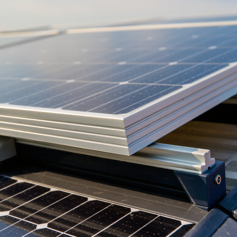
6063-T5 is a common aluminum alloy for solar-panel frame extrusions. It combines useful strength with relatively low weight and can be shaped into long, consistent sections. The T5 temper means the extrusion is artificially aged after cooling from the forming process. Typical profiles include panel-edge channels, mounting rails, and corner sections. Their small lips and grooves help hold glass and connect frame parts. Details matter.
A well-designed profile balances stiffness, fit, and material use. Check wall thickness, corner geometry, and the specified dimensional tolerances against the panel design. Anodizing can add surface protection, but it does not make aluminum immune to wear or poor drainage. Water trapped in a narrow channel can still create problems over time.
Tips: Inspect a cut sample. Look for clean edges, even walls, and drainage paths that will not be blocked after assembly.
Do not select an extrusion by alloy and temper alone. Loads, span, fastener placement, and contact with other materials all affect performance. A profile that feels rigid in a short sample may flex across a longer panel edge. That is easy to overlook. Confirm the dimensions and finish with the frame supplier, and test the assembled design under expected conditions.
| Profile or Design Feature | Typical Form or Dimension | Material / Physical Data | Role in a Solar Panel Frame | Practical Design Notes |
|---|---|---|---|---|
| 6063-T5 frame extrusion | Custom hollow or semi-hollow perimeter section; dimensions are set to suit the module and mounting system. | 6063 is an aluminum-magnesium-silicon alloy. T5 indicates artificial aging after cooling from the extrusion process. Aluminum density is approximately 2.70 g/cm³. | Provides a lightweight structural edge around the glass-and-cell laminate and supports attachment to mounting hardware. | Strength depends on section geometry, wall thickness, temper, and applicable product specifications; verify design loads and material certificates. |
| Frame depth | Common module-frame depths are roughly 30–40 mm; actual dimensions vary by module design. | Not a fixed alloy property; determined by the extrusion cross-section. | Contributes to frame stiffness and provides a side wall around the laminate edge. | Check compatibility with clamps, rails, drainage paths, and the module’s installation instructions. |
| Extrusion wall thickness | Often designed in the approximate 1.2–2.0 mm range for frame walls, depending on the section and load requirements. | 6063 alloys are well suited to complex extruded shapes and thin-wall section design. | Balances rigidity, weight, material use, and manufacturability. | This is a design range, not a universal requirement. Structural analysis and testing should determine the final thickness. |
| L-shaped perimeter profile | Typically has a broad base and a raised retaining lip; the cross-section is customized for the laminate stack. | Commonly produced as a continuous 6063-T5 extrusion and cut to length. | Locates and supports the module laminate along the frame perimeter. | Allow for sealant or gasket placement and avoid sharp contact against glass edges. |
| Hollow or ribbed profile | Internal cavities or ribs may be incorporated into the cross-section. | Extrusion geometry can add stiffness without making the entire section solid. | Improves section efficiency and can provide features for clips or fasteners. | Check die feasibility, dimensional tolerances, corner joining, and water drainage. |
| Corner connection | Common approaches include internal corner keys, screws, or other mechanical joining methods. | Connection hardware is separate from the extrusion alloy. | Joins the four cut profile lengths into a rectangular frame. | Corner strength and fit depend on profile geometry, machining, hardware, and assembly quality. |
| Surface finish | Mill finish or an applied finish such as anodizing may be specified. | Aluminum naturally forms a thin oxide layer; finishing requirements depend on the environment and appearance needs. | Provides the required surface appearance and can support durability requirements. | Specify finish, color, and inspection criteria; protect finished surfaces during transport and assembly. |
| Corrosion and outdoor exposure | Profile design should include suitable drainage and avoid water-trapping details. | Aluminum generally has good atmospheric corrosion resistance, but performance depends on exposure and contact materials. | Helps the frame withstand outdoor service conditions. | Consider coastal exposure, galvanic contact with dissimilar metals, coatings, and drainage when selecting materials and details. |
| Thermal behavior | Frame length and connection details should accommodate temperature-related movement. | Aluminum’s coefficient of thermal expansion is approximately 23 × 10−6/°C. | Allows the frame and connected components to respond to temperature changes. | Account for expansion in module, rail, and clamp design; use the module manufacturer’s installation guidance. |
Dimensions shown are representative design ranges, not universal specifications. Final profile geometry and material requirements depend on module construction, structural loads, applicable standards, and installation conditions.


