Main Menu
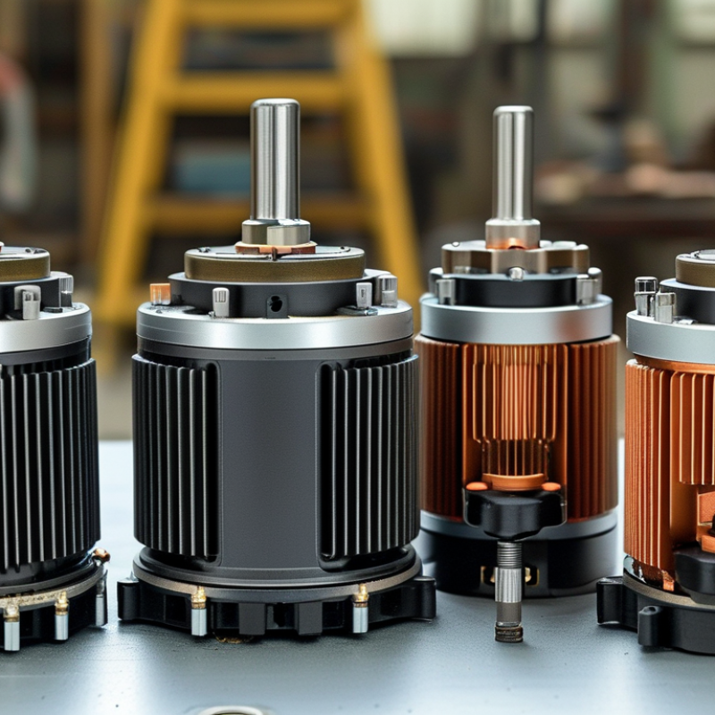
Choosing among the different kinds of dc motors is no longer a simple catalog exercise. Global buyers in 2026 must match motor design with load, control method, duty cycle, and installation conditions. A compact brushed motor may drive a window actuator reliably. A brushless DC motor may deliver quieter operation and longer service in a cooling fan. A geared DC motor can provide strong low-speed torque, but it may introduce backlash, noise, and extra maintenance points.
Austin Hughes, a respected motor-drive author, states, “The motor must suit the load, the control method, and the working environment.” This practical principle remains valuable for engineers, procurement teams, and equipment manufacturers. It also prevents a common mistake: choosing by rated power alone. Voltage stability, starting current, speed range, thermal limits, shaft alignment, and enclosure protection can change real-world performance.
Details decide outcomes.
This guide examines brushed, brushless, geared, coreless, permanent-magnet, and other widely used DC motor designs. Each section considers operating behavior, advantages, weaknesses, typical applications, and purchasing concerns. Global sourcing also requires careful attention to documentation, testing records, quality consistency, and after-sales support. A low unit price may look attractive. It can become expensive when replacement rates rise or control compatibility fails.
Some comparisons remain imperfect. Manufacturers may use different test conditions, and datasheets rarely reveal every startup response or vibration issue. Therefore, buyers should confirm samples under actual loads before committing to large orders. The best motor is not universally powerful. It is appropriately engineered, honestly specified, and dependable in its intended environment.
DC motors convert electrical energy into controlled mechanical motion. A magnetic field interacts with current in the armature, creating torque. Brushed motors use mechanical commutation, while brushless motors use electronic switching. This difference affects maintenance, noise, efficiency, and control complexity. In industrial systems, motors drive conveyors, pumps, valves, fans, and automated positioning equipment. Their performance can influence an entire production line.
Global buyers should examine voltage, torque, speed range, duty cycle, insulation class, and enclosure protection. A geared DC motor suits applications requiring strong low-speed movement. A servo motor offers precise positioning and rapid response. Brushless designs often support longer service intervals in dusty or continuous-duty environments. However, no motor fits every installation. I have seen selections fail because engineers checked rated power but ignored startup current, ambient temperature, or load inertia. Testing under real operating conditions remains essential.
Tips: Measure the load before choosing a motor. Check stall current and controller compatibility. Confirm shaft dimensions and mounting space. Review applicable safety and electromagnetic compatibility requirements for the target market. Keep spare brushes or sensors when maintenance access is limited. A small efficiency gain may matter greatly across thousands of operating hours.
For global buyers in 2026, DC motor selection should begin with construction, not marketing labels. A useful division separates brushed motors from brushless motors. Brushed DC motors use rotor windings, a commutator, and carbon brushes to switch current mechanically. They are simple, responsive, and often economical. Brush wear matters.
Permanent-magnet DC motors provide compact torque, while wound-field motors allow field-strength adjustment. Series, shunt, and compound field designs suit different starting and speed behaviors.
This classification becomes important when loads change sharply, such as conveyors, pumps, or lifting equipment.
Commutation creates another practical boundary. Mechanical commutation depends on brush contact and precise timing between coils. It can produce electrical noise and requires inspection in dusty or high-cycle environments.
Electronic commutation uses sensors or sensorless control with switching electronics. Brushless motors usually deliver longer service life, lower maintenance, and efficient continuous operation.
However, the controller is not optional. Its voltage range, current capacity, and control logic must match the motor. A mismatch may cause heat, vibration, or failed starting.
A neat classification can mislead. Some motors combine permanent magnets, special windings, and feedback devices. Check rated torque, speed range, duty cycle, insulation class, and ambient temperature before comparing prices.
Request test data, wiring details, and protection ratings from the supplier. Do not assume a familiar voltage works everywhere.
Regional power systems, machine standards, and service skills can change the real operating cost. Even a well-matched motor may expose overlooked assumptions during commissioning.
For global buyers, understanding operation matters more than comparing labels. A brushed DC motor uses armature current and magnetic fields to create torque. Its speed usually follows applied voltage, while load changes reduce speed. Pulse-width modulation, or PWM, adjusts average voltage efficiently. However, brushes wear under dust, heat, and frequent reversing.
A brushless DC motor replaces mechanical brushes with electronic commutation. A controller switches phase current according to rotor position. Hall sensors improve starting and low-speed control, while sensorless control can reduce hardware costs. Field current also shapes speed in wound-field motors. In real commissioning, incorrect PWM frequency can create noise, heating, or weak starting torque. The IEA 4E Motor Systems Annex reports that motor systems consume about 53% of global electricity. Small control losses can therefore become expensive across large fleets.
Tips: Match the controller to motor voltage, rated current, feedback method, and braking needs. Check continuous torque, not only peak torque. Test the motor under its real load. A laboratory result may not survive conveyor dust or cold starts. IEC 60034 guidance supports consistent motor performance testing, but installation conditions still require engineering judgment. I would not choose sensorless control for every application; low-speed accuracy may be disappointing. Record acceleration time, temperature rise, and speed error before approving production.
| DC Motor Type | Operating Principle | Typical Speed Range | Speed-Control Method | Starting Torque | Typical Efficiency | Main Advantages | Limitations | Common Applications | Buyer Selection Considerations |
|---|---|---|---|---|---|---|---|---|---|
| Permanent-Magnet Brushed DC Motor | A permanent-magnet stator creates the stationary magnetic field, while a wound armature produces torque through a mechanical commutator and carbon or metallic brushes. | Approximately 1,000–10,000 rpm, depending on voltage, winding, load, and motor size. | Pulse-width modulation (PWM), adjustable DC voltage, or closed-loop feedback. PWM is commonly used because it maintains useful torque at reduced average speed. | Medium to high; approximately 2–5 times rated running torque can be available for short periods, subject to thermal and mechanical limits. | Typically 60–85% for small and medium motors. | Simple drive electronics, low initial cost, good low-speed torque, and easy reversal by changing polarity. | Brush and commutator wear, electrical arcing, audible noise, electromagnetic interference, and limited service life in demanding environments. | Small pumps, fans, actuators, office equipment, battery-powered tools, toys, and light automation. | Check brush life, duty cycle, stall protection, allowable PWM frequency, noise limits, operating temperature, and replacement accessibility. |
| Separately Excited DC Motor | The armature and field winding are supplied by electrically separate sources, allowing independent control of armature voltage and field current. | Approximately 500–3,000 rpm in standard industrial configurations; higher speeds are possible with suitable mechanical design. | Armature-voltage control provides constant-torque operation below base speed. Field weakening provides approximately constant-power operation above base speed. | High and highly controllable; starting torque is set by armature current and field strength. | Typically 75–93%, depending on rating, speed, and field losses. | Wide speed range, precise torque control, and flexible operation in four-quadrant drive systems. | Requires a separate field supply, larger control system, brushes, commutator maintenance, and careful field-loss protection. | Test stands, rolling equipment, elevators, hoists, large conveyors, and legacy variable-speed industrial drives. | Confirm field-supply requirements, minimum field current, drive regeneration capability, overspeed protection, and maintenance resources. |
| Shunt-Wound Brushed DC Motor | The field winding is connected in parallel with the armature, so field current remains relatively stable as the load changes. | Approximately 500–3,000 rpm, with comparatively small speed variation from no-load to rated-load operation. | Armature-voltage control for below-base-speed adjustment; field weakening can extend speed above the base value. | Medium; generally lower than a series-wound motor but suitable for loads that do not require extreme starting torque. | Typically 75–92% for industrial-sized motors. | Good speed regulation, stable operation, and suitable performance for continuous-duty loads. | Brush maintenance, lower starting torque than series motors, and possible overspeed if the field circuit is interrupted. | Machine tools, fans, centrifugal pumps, paper-processing equipment, and constant-speed conveyors. | Provide field-loss protection, verify continuous-duty cooling, and match the motor's speed regulation to the load profile. |
| Series-Wound Brushed DC Motor | The field winding is connected in series with the armature, so the same current flows through both circuits and magnetic flux increases with load current until saturation. | Approximately 500–5,000 rpm under load; speed can rise dangerously at no load. | Armature voltage, PWM, or a series resistor for basic control. A controlled drive is preferred for safe speed regulation. | Very high; often suitable for heavy starting loads and rapid acceleration. | Typically 75–90% near rated load. | Exceptional starting torque, compact torque-producing design, and good short-term overload capability. | Unsafe at no load, poor speed regulation, brush wear, commutator arcing, and limited suitability for precision speed control. | Traction equipment, cranes, hoists, lifts, winches, and older starter or propulsion systems. | Use mechanical or electronic overspeed protection, ensure the motor cannot operate unloaded, and verify the duty cycle carefully. |
| Compound-Wound Brushed DC Motor | Combines shunt and series field windings. The shunt field improves speed regulation while the series field increases starting torque. | Approximately 500–3,000 rpm, depending on the compound connection and design. | Armature-voltage control, PWM, and field weakening. The control strategy must account for both field circuits. | High; normally higher than a shunt motor and lower or more controlled than a pure series motor. | Typically 75–92%. | Balanced torque and speed regulation for variable-load machinery. | More complex winding and control requirements, brush maintenance, and possible instability if incorrectly connected. | Presses, elevators, conveyors, compressors, shears, and heavy machine tools. | Specify cumulative or differential compounding, starting-load profile, overload duration, and field-connection requirements. |
| Brushless DC Motor (BLDC) | Permanent magnets are mounted on the rotor, while electronically switched stator windings create a rotating magnetic field. Electronic commutation replaces brushes and a mechanical commutator. | Approximately 1,000–30,000 rpm; specialized designs can operate outside this range. | Six-step trapezoidal commutation, PWM duty-cycle control, Hall-sensor feedback, sensorless back-EMF control, or field-oriented control (FOC). | High, but it depends on controller current limits, rotor position feedback, and thermal capacity. | Typically 80–95%; high-quality systems can exceed 90% across a broad operating region. | High efficiency, long service life, low maintenance, quiet operation, high power density, and accurate electronic control. | Requires a compatible electronic controller, position sensing or a sensorless algorithm, electromagnetic-compatibility design, and protection against overheating or demagnetization. | Electric mobility, robotics, HVAC blowers, drones, pumps, medical equipment, appliances, and automated production systems. | Match motor phase count, controller voltage, continuous and peak current, Hall-sensor sequence, feedback type, IP rating, and regenerative-braking capability. |
| Coreless or Ironless Brushed DC Motor | The rotor uses a lightweight self-supporting winding without a conventional iron core. A permanent-magnet stator provides the magnetic field, and brushes provide mechanical commutation. | Approximately 2,000–20,000 rpm, depending on diameter, winding, and load. | PWM, adjustable voltage, current limiting, and closed-loop speed control. Acceleration and deceleration should be limited to protect the lightweight rotor. | Low to medium continuous torque, with very fast acceleration because of low rotor inertia. | Typically 60–85%; short-term dynamic response is often more important than peak efficiency. | Very low inertia, rapid response, low cogging torque, low electrical inductance, and smooth motion. | Lower continuous thermal capacity, brush wear, possible high current ripple, and sensitivity to excessive acceleration or stall conditions. | Camera mechanisms, compact medical devices, precision instruments, miniature pumps, and fast positioning systems. | Check permissible peak current, stall time, brush rating, rotor balance, acceleration limit, and required motion smoothness. |
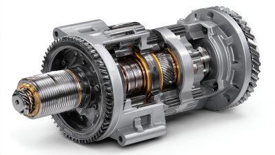
| Geared DC Motor | A brushed or brushless DC motor drives a gearbox, usually using spur, planetary, worm, or helical gears to reduce speed and increase output torque. | Motor speed may be 1,000–30,000 rpm; gearbox output is commonly approximately 5–500 rpm. | Motor PWM, voltage control, current control, and encoder-based closed-loop control. Output speed is determined by motor speed divided by the gear ratio, subject to slip and load. | High output torque after reduction; gearbox efficiency and allowable peak torque must be included in calculations. | Approximately 50–90% for the complete motor-and-gearbox assembly, depending strongly on ratio, gear type, lubrication, and load. | High output torque, compact packaging, lower output speed, and easy integration with position or speed feedback. | Gear noise, backlash, wear, limited shock-load capability, reduced efficiency, and possible thermal buildup at low output speed. | Electric actuators, automated doors, conveyor drives, valve actuators, AGVs, robotics, and positioning mechanisms. | Calculate continuous and peak output torque, gear ratio, backlash, radial and axial loads, gearbox service life, lubrication, and brake requirements. |
| Tubular Linear DC Motor | Converts electrical energy directly into linear force using permanent magnets and electronically switched or mechanically commutated windings, eliminating a rotary-to-linear transmission. | Linear speed is commonly approximately 0.1–5 m/s; force and speed depend on stroke, cooling, and drive design. | PWM current control, force control, position feedback, and closed-loop servo control. Current is the primary variable for force production. | High peak force is available from zero speed, subject to continuous-force and thermal limits. | Typically 70–95% for the motor and drive system, depending on operating point. | Low mechanical backlash, direct linear motion, rapid response, and reduced transmission maintenance. | Requires accurate guidance, position feedback, thermal management, and protection from side loads and contamination. | Pick-and-place equipment, semiconductor machinery, packaging systems, precision stages, and automated inspection equipment. | Specify continuous and peak force, stroke, travel speed, duty cycle, guidance accuracy, encoder resolution, and cooling method. |
Note: The performance figures are typical engineering ranges for comparison only. Actual values depend on motor size, winding design, supply voltage, controller settings, cooling, duty cycle, ambient temperature, load inertia, and application-specific safety limits.
Choosing a DC motor in 2026 requires more than checking rated speed. Application conditions decide whether performance claims matter.
Brushed DC motors offer simple control and strong starting torque. Their brushes wear against the commutator, especially during frequent starts. Maintenance is predictable.
Brushless DC motors reduce mechanical wear and usually deliver higher efficiency. They need electronic control, however, which increases system complexity.
Gearmotors trade speed for usable torque. They suit conveyors, actuators, and compact positioning equipment. Coreless designs respond quickly, but their thermal capacity may be limited.
Efficiency depends on load, voltage, cooling, and controller quality. A motor running far below its rated load can waste energy through poor matching.
Small details matter.
Measure current during startup, steady operation, and stalled conditions. Do not trust a catalog figure alone.
For global buyers, verify insulation class, ingress protection, duty cycle, noise limits, and replacement access.
Ask for test conditions behind efficiency data. Confirm whether service parts can cross borders without long delays.
In practice, the cheapest motor is rarely the cheapest installation. A sealed unit may resist dust, yet become difficult to repair.
I have seen teams overvalue peak torque and overlook heat buildup. That mistake can shorten bearing life. Keep temperature and current records during commissioning.
Global buyers choose DC motors by application, not by headline power ratings. A small conveyor may need steady torque, while a camera gimbal needs quiet, precise movement. Start with load torque, target speed, voltage, duty cycle, and available space. Measure the real load when possible. Catalog estimates can mislead.
Brushed DC motors suit cost-sensitive equipment with simple speed control. They work well in pumps, toys, valves, and light industrial mechanisms. Brushless DC motors fit continuous-duty systems, fans, compressors, and battery equipment. They usually offer longer service life and lower electrical noise, but require suitable electronic control. Geared DC motors provide higher output torque at lower speed. Check gearbox backlash before selecting one for positioning tasks. Coreless motors respond quickly and can reduce moving mass in portable instruments. Keep it practical.
Temperature, dust, humidity, and vibration also affect the choice. A motor that performs well in a clean laboratory may struggle inside a hot enclosure. Buyers should verify insulation class, ingress protection, shaft load, connector design, and expected service hours. Confirm rated performance at the actual supply voltage, especially in battery-powered products. Noise matters too. Sometimes a slightly larger motor runs cooler and lasts longer than a compact option operating near its limit. That choice may increase cost, yet undersizing often creates more trouble through overheating, unstable speed, and early maintenance. Testing one sample under real operating conditions remains wiser than trusting specifications alone.
Office: (281) 855-2218
Copyright © 2025 Telco Intercontinental Corp. All rights reserved. Privacy Policy | Legal Disclaimer
Telco®, TelcoMotion®, and TelcoGreen® are registered trademarks of Telco Intercontinental Corp.